


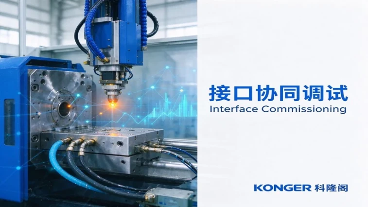
On a new machine or a new line, the familiar scene is this: pressure, speed and position are all tuned, and the parts still will not hold steady — short shots, drifting dimensions and failed robot take-out in turn. The problem is usually not the machine but the interfaces between the machine and the mould, the auxiliary equipment and the automation. Based on Konger's experience in machine delivery and after-sales support, this article covers six interface problems and how to handle them.
1. Why interface problems are easily missed
Responsibility is split across suppliers
Machine, mould, auxiliary equipment and automation come from different suppliers. When an interface fails, no one on site owns it.
Interface parameters are invisible
Flow rate, supply temperature, signal polarity, action sequence and take-out position are not printed on the machine parameter sheet, yet they decide whether production runs steadily.
A machine acceptance test does not prove the line is ready
The machine dry-cycles correctly and a single trial shot passes; the problems appear only once the auxiliary equipment and automation are connected. Acceptance has to be defined for the whole line.
2. Six interface problems and how to handle them
2.1 Mould water circuit: reversed, low flow, cross-flow
Reversed supply and return disturb the mould's cooling sequence; uneven distribution across cavities on a multi-cavity mould causes local overheating; cross-flow lets neighbouring circuits interfere. Check the direction against the nameplate, measure return temperature circuit by circuit, and add a manifold with flow meters where needed.
2.2 Temperature controller and hot runner: slow heating, large deviation, broken thermocouple alarms
Heating power that does not match the mould's thermal mass, or hot-runner zones wired to the wrong controller circuit, both look like "the temperature will not come up". Confirm total heating power against the mould requirement first, then match each thermocouple to its heating circuit zone by zone.
2.3 Drying and feeding: under-dried material, bridging, regrind ratio
Material that was not dried sufficiently shows silver streaks; bridging in the hopper starves the feed and is often read as insufficient injection capacity; a changed regrind ratio alters flowability and shrinkage. Set drying temperature and time to the material, check the hopper and loader lines, and fix the regrind ratio and record it.
2.4 Cooling circuit: temperature fluctuation, flow distribution, condensation
Unstable cooling-water temperature makes dimensions drift; uneven cooling across cavities creates cavity-to-cavity differences; high humidity causes condensation on the mould face and affects appearance. Stabilise the chiller outlet temperature and distribute flow by cavity.
2.5 Robot and mould-open signal: take-out position, position signal, cycle mismatch
A mould-open position that does not match the robot's pick height causes failed picks or mould collisions; a "mould open" signal taken from a position switch instead of pressure build-up makes the robot move too early; ejection and gripper timing out of step drops parts. Confirm each signal's actual trigger point in manual single-step first, then tune the cycle in linked operation.
2.6 Safety circuit and mould-change interface: false trips, incomplete reset
A loose safety-gate limit switch, an interrupted light curtain, or an incomplete emergency-stop reset all stop the machine in automatic mode; after a mould change the mould ID and the recalled parameter set do not correspond, so "the parameters are still the previous mould's". Verify each safety signal, and check mould number against parameter set after every change.
3. A sensible order for interface commissioning
Static confirmation first
Check wiring, pipe direction, nameplates and signal polarity with power off and no movement — confirm only that it is connected correctly.
Single-action confirmation next
Water through the circuit and return flow observed, temperature rise observed on the curve, robot position checked in single step. Verify each item alone, with no other variables in play.
Interlocks and cycle last
Only when every single action is correct, run the line linked, watch at least ten shots, and confirm a stable cycle with no interference and no alarms.
4. How Ningbo Konger supports this coordination
Ningbo Konger Machinery Co., Ltd. is based in Ningbo, founded in 2013, and covers the development, manufacture, sales and service of injection molding machines. The range is built around the K-TEC servo energy-saving series, with CMS (Color Mixing System) two-colour and sandwich machines, plus dedicated configurations for PET preforms, artificial flowers, TPR soft compounds and flame-retardant nylon — close to thirty customised models in total.
For interface commissioning, that means:
A stable machine side. K-TEC uses a split three-platen structure with thickened platens, so clamp force travels a short path, and the servo hydraulic system supplies oil on demand with a closed-loop pressure response. With the machine side not drifting, interface problems surface clearly instead of hiding behind machine variation.
Models matched to the material. Screw, nozzle and temperature configuration follow the material, so drying and mould-temperature conditions line up more readily and a material change does not force a full re-tune.
Parameters that can be stored and recalled. Process and mould parameters can be saved and called up, so after a mould or line change the historical values can be compared to tell an interface change from a machine change.
Development, production, sales and service in one system. From selection and matching to installation and after-sales, the chain stays inside one organisation, so interface issues do not have to be pushed back and forth between suppliers.
5. Interface commissioning checklist
Do mould supply and return directions match the nameplate?
Has the return temperature of each circuit been measured separately?
Does the temperature controller's power match the mould's thermal mass?
Have hot-runner zones been matched to controller circuits one by one?
Are drying temperature and time set for the material?
Is the mould-open signal taken from position or from pressure?
Does the robot pick height match the mould-open position?
After a mould change, does the parameter set match the mould number?
Conclusion
The last mile of commissioning is rarely on the machine itself. Confirm the six interfaces — water, temperature, feeding, cooling, signals and safety — one by one, and the machine's capability actually reaches the part. Konger's work on structural rigidity, servo hydraulics and dedicated model configuration is, in essence, providing a steady datum for that interface chain.