


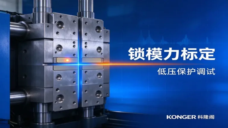
Clamping force set too low shows up as flash and drifting dimensions; set too high, the parting line and tie bars carry an overload for months. Getting calibration and low-pressure mold protection right during installation and commissioning is far cheaper than chasing process parameters afterwards. This article stays on the clamping unit: how to estimate projected area, how to calibrate clamping force on site, how to step the low-pressure protection, and what to re-check after leveling — with the structural choices Konger makes in its K-TEC series.
1. Where the Clamping Force Figure Comes From
1.1 Count the whole projected area
Clamping force is estimated from the projected area of the part in the opening direction. For multi-cavity molds, multiply by the number of cavities, and include the runner and gate area. The usual omission is the clearance zone for sliders and lifters, plus any overflow surface: the real pressurized area often runs 10–20% larger than the part area on the drawing.
1.2 Start at the lower bound of specific pressure
The specific clamping pressure per unit area depends on material flow and wall thickness. Easy-flowing grades such as PS and PP typically need 300–500 kg/cm²; ABS and PMMA around 400–600 kg/cm²; engineering grades such as PA and PC often sit at 600–900 kg/cm². These are empirical ranges — check them against the material supplier's data and the runner pressure drop. Thinner walls and longer flow paths push you toward the upper bound.
Clamping force (t) ≈ projected area (cm²) × specific pressure (kg/cm²) ÷ 1000. What you get is an upper reference, not a setpoint. It has to be corrected by measurement once the mold is in the machine.
1.3 Never treat the rated force as the working force
Running above 90% of rated clamping force for long periods brings fatigue in platens and tie bars forward. Keep the working force at 70–85% of the rating, which leaves room for thermal growth of the mold and normal wear.
2. Calibration: Turning the Nameplate Number into a Real Number
2.1 Three field methods
- Clamping force gauge: a pressure-sensing pad between the moving and fixed platens gives a direct reading. The most intuitive option, well suited to small and medium tonnage.
- Tie-bar elongation: strain gauges or a measuring bar capture elongation at clamp-up and convert it to load. Best for large tonnage and split-frame designs.
- Standard test block: a block of known area plus the hydraulic pressure reading validates the conversion factor between pressure and clamping force.
2.2 Uneven corners are the first failure
If the four corners differ by more than 10% at clamp-up, the problem is template parallelism or tie-bar preload — a single total-force number tells you nothing at that point. The correct order is a no-load parallelism check first, then per-corner force measurement.
2.3 Record a baseline
After calibration, log hydraulic pressure, clamping force reading, mold height, corner deviation and oil temperature. Re-measure after a mold change or three months of running; a deviation above 5% means checking platens, the toggle mechanism and lubrication.
3. Low-Pressure Mold Protection: The Last Line of Defence
3.1 Step it, don't run full pressure
Close in three stages: a fast approach at low pressure and high speed, a slow stage as the mold faces come close, and a contact stage at minimum pressure. Set the protection pressure threshold at roughly 1.2–1.5 times normal clamping pressure, and the time threshold at about 1.5 times normal closing time — always confirmed against the measured curve.
3.2 Cover ejectors, sliders and runners
Left-over parts or runner, ejector pins that did not return, a stuck slider — each loads the protection stage early. Wire the ejector-return signal into the closing condition instead of relying on the time window alone.
3.3 Prove it with a test block
Place a 0.5–1 mm sheet of paper or a standard test block between the platens: the machine must alarm and stop immediately. Remove it and closing must run normally. Only after that one-in-one-out test does the protection actually work.
4. Two Checks That Belong to Installation
4.1 Template parallelism
After the machine is in place and leveled, measure the four corner distances between moving and fixed platens with an inside micrometer or a dedicated gauge. Keep the deviation within 0.1 mm. This must be done unloaded and without a mold — measuring with a mold in place only hides frame distortion.
4.2 Mold height and clamping
If mold height is set wrong, clamping force ends up loading the toggle instead of the mold, and you see force that will not build plus difficult opening. After adjusting mold height, verify the clamping force reading rather than trusting the scale.
5. How Konger K-TEC Approaches the Clamping Unit
- Rigid clamping structure: the K-TEC series (K-TEC120, K-TEC170, K-TEC1200 and others) uses a split three-platen design with reinforced platens. The force path is short, platen deflection stays small over years of running, and the calibration baseline drifts less.
- Stable pressure loop: servo-driven hydraulics supply oil on demand, so pressure ripple during closing and holding is tighter. Clamping force repeats more consistently and the protection threshold is less likely to false-trigger.
- Reusable parameters: process and mold parameters can be saved and recalled, so a mold change does not start from zero pressure testing.
- Specialized platforms: CMS multi-color machines, plus dedicated configurations for artificial flowers, TPR soft compounds and flame-retardant nylon, match the clamping unit to the part and the mold instead of forcing a general-purpose machine onto a difficult process.
6. Quick Field Checks
- Short shots and flash: re-check projected area and specific pressure first, then confirm hydraulic pressure and toggle wear.
- Noise during clamping: usually insufficient tie-bar lubrication or parallelism out of tolerance — verify parallelism, then lubricate.
- No clamp or clamping interrupted: check whether the protection threshold is too tight and whether the ejector-return signal is missing.
- Difficult opening: mold height over-adjusted or clamping force set too high; back off 5–10% and re-measure.
Conclusion
More clamping force is not more safety. Estimate projected area and specific pressure, calibrate the real force on the machine, then hold the mold with a stepped low-pressure protection. With those three done, commissioning a horizontal injection molding machine has a stable base. Konger's K-TEC design — rigid platens and a closed-loop pressure system — is aimed at keeping that calibration from drifting over years of production.