


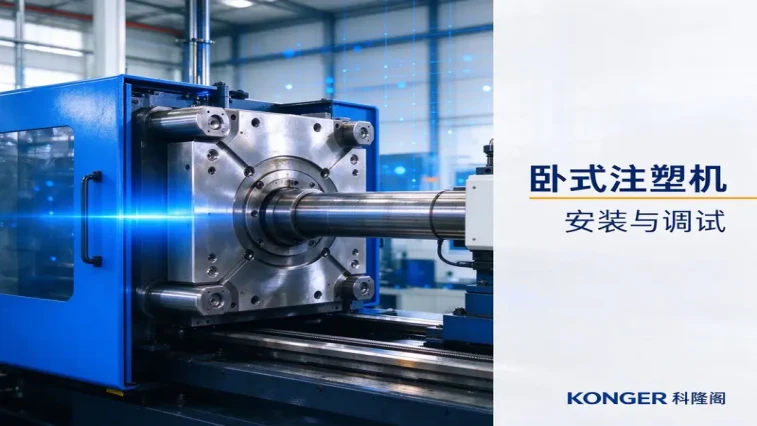
The installation and commissioning of a horizontal injection molding machine determines the upper limit of its stability over the next five to ten years. The same machine, with a foundation miscalculated by a few millimeters, insufficient releveling checks, or mold clamping force set by hand, may result in final product defect rates differing by several times. This article dissects the complete technical path of a horizontal injection molding machine from placement, leveling, line connections to material testing, following the on-site construction sequence, and combines the structural characteristics of the Konger (NingBo Konger) model to explain which steps can be relieved by the equipment design itself.
One, Confirmation of On-site Conditions Before Installation
1.1 Foundation and Load-bearing
The weight of a horizontal injection molding machine is concentrated in the mold clamping unit and the injection unit, with the foundation load not being evenly distributed. Before installation, the total weight of the equipment and the point load should be verified. The concrete foundation strength should not be less than C25, and the thickness should be reserved according to the machine's tonnage, generally not less than 200 mm; soft ground requires or steel plate diffusion treatment. The positional error of the foundation bolt reserved holes should be controlled within ±5 mm, otherwise, only shims can be used for compensation in the later stage, making the machine body level difficult to stabilize.
1.2 Three Routes of Water, Electricity, and Gas
Power: Reserve 1.2 times the rated power, independent circuit, phase sequence must be measured on-site, not assumed.
Cooling Water: Suggested inlet temperature of 20–25 ℃, flow rate matched to the tonnage, return pipe diameter must not be smaller than the inlet pipe diameter, avoiding back pressure leading to high oil temperature.
Compressed Air: 0.6–0.8 MPa, require a cold dryer and three-stage filtration, moisture-containing air sources will directly damage pneumatic valves and mold temperature control components.
Two, Three Key Nodes of Mechanical Installation
2.1 Leveling and Shock Absorption
After the equipment is placed, perform a rough leveling, then use foundation shims for fine adjustment. Longitudinal and transverse level should be controlled within 0.05 mm/m, and four corners should be synchronously rechecked; recheck once 24 hours after adjustment is completed to allow the foundation and shims to complete stress release. The hardness of the shock absorber pad should match the machine weight; too soft will cause the entire machine to vibrate during mold clamping, while too hard will make vibration isolation ineffective.
2.2 Mold Parallelism and Choke Pin
Mold parallelism is the lifeblood of the mold clamping unit. After installation, measure the parallelism of the movable and fixed molds and the diagonal deviation of the choke pin; exceeding tolerance will cause unilateral mold pressure and early wear of guide pins. This step must be completed under no-load conditions; adjusting with the mold will only mask the problem.
2.3 Barrel and Screw Assembly
Before installing the screw into the barrel, check the straightness and surface plating, avoiding collisions during assembly; the barrel heating ring should be uniformly attached, and the thermocouple insertion depth should be correct. Otherwise, the deviation between the temperature display and the actual material temperature can reach tens of degrees, enough to ruin the entire process curve.
Three, Commissioning Process: From No-Load to Material Test Molding
3.1 No-Load Operation and Hydraulic Venting
First, run at low speed under no load, observe whether pressure builds steadily and whether there are any abnormal noises; the hydraulic system must be vented according to regulations, incomplete venting will be manifested as slow pressure rise and delayed action.
3.2 Temperature Curve and Material Matching
Set segmented temperatures according to the recommended range by the raw material supplier, increasing from the rear to the front of the barrel, and the nozzle slightly lower than the front by 5–10 ℃ to prevent dripping. After reaching the temperature, maintain it for 20–30 minutes before feeding, allowing the barrel to reach thermal equilibrium and stabilize.
3.3 Mold Clamping Force and Low-Pressure Protection
Mold clamping force is estimated based on the projected area of the product and the material pressure, lower is better, excessive clamping will cause long-term overloading of the mold and template. Low-pressure protection must be set segment by segment: first, close the mold with low speed and low pressure to determine the true contact position of the mold, then narrow the protection pressure and time to just pass it. This is the most effective line of defense for protecting the mold, but also the most easily omitted step.
3.4 Injection Parameters and First Mold Validation
Use the short shot method for the first mold to determine the injection position, then gradually increase pressure and extended holding, observing the stable range of product weight and appearance. Record the process parameters of each mold to form a reproducible process card, providing a basis for subsequent shift and material changes.
Four, Engineering Advantages of the Konger Model
In the above steps, much of the work relying on the craftsmanship of the master can be absorbed by the equipment design in advance:
High Rigidity Mold Clamping Structure: K-TEC series (including K-TEC120, K-TEC170, K-TEC1200 and other models) adopts a split three-plate structure and thickened templates, with a short mold clamping force transmission path, small template deformation under long-term operation, and better retention of leveling and parallelism.
Multi-Stage Precise Temperature Control: PID control of barrel zones combined with high-response heating rings narrows temperature fluctuations, significantly reducing the time spent repeatedly testing temperatures during commissioning.
Servo Energy-Saving Hydraulic: Oil supply as needed, reducing energy consumption during holding and cooling stages, simultaneously lowering the entire machine's noise and oil temperature, making it more environmentally friendly for the workshop.
Specialized Model Coverage: CMS series (such as CMS360, CMS450-3Color) can cover multi-color products; for special materials like simulated flowers, TPR soft rubber, and flame-retardant nylon, Konger provides specialized configurations, matching the compression ratio of the screw and barrel, and mixing sections to material characteristics, reducing the dilemma of machine generalization and difficult-to-adjust processes.
Modularization and Maintenance Convenience: Hydraulic and electrical control components are laid out in a modular manner, making daily inspection and fault location paths clear, with technical support ensuring controllable commissioning cycles.
Five, Quick Reference for Common Commissioning Issues
Product Shortage, Shrinkage: First, increase injection pressure and holding time, then consider material temperature, raising temperature will mask the actual pressure shortage.
Severe Flashing: Recheck mold clamping force and projected area calculation, check if the mold parting surface is worn.
Dimension Instability: Check thermocouple contact tightness, material temperature fluctuations, and cooling water flow rate.
Difficulty in Ejection: Confirm demolding angle, gradually increase ejection force in segments, avoiding ejecting all at once.
Conclusion
The installation and commissioning of a horizontal injection molding machine essentially means straightening out three lines: mechanical precision, thermal balance, and pressure control. Solid leveling, parallelism, and low-pressure protection lay the foundation for subsequent parameter adjustments. Konger's focus on mold clamping rigidity, temperature control precision, and specialized configurations ensures this line remains stable during long-term production.